


Please Leave Us A Message
Privacy statement: Your privacy is very important to Us. Our company promises not to disclose your personal information to any external company with out your explicit permission.

Yetnorson
 July 12, 2022
With the rapid development of satellite radio navigation services, more and more countries are beginning to develop their own navigation communication systems. Due to the limited spatial distribution of satellites of various navigation communication systems, in low-information, small-capacity satellite navigation communication systems, the antennas of the terminals used are required to have small volume, low loss, polarization polarization, and elevation plane. The width and pattern are omnidirectional. Although single-arm helical antennas and quadrifilar helical antennas are often used, single-arm helical antenna gains are 2 dB lower than dual-arm helical antennas. Four-arm helical antennas require feeders of 0°, 90°, and 180°, respectively. , 270 °, which is bound to require a more complex feed network, and the dual-arm helical antenna just makes up for their shortcomings. By adjusting the physical parameters of the spiral, the shaped beam of the main lobe pointing to the satellite can be obtained, so the dual-arm helical antenna becomes a suitable choice in the satellite navigation communication system.
According to the requirements of the satellite navigation communication system, the antenna design of the terminal needs to meet the following points: the antenna coverage is from 0° to 360°, the zenith angle is 20° to 58°, and the center gain of the lobe is 5.5 dBi. The gain at ±19° at the center point is 2.5 d Bi. In addition, the axial ratio of the right-hand circularly polarized wave is less than 3 dB, and the voltage standing wave ratio is less than 1.5 in a frequency band of less than 1%. Due to special application requirements, the antenna used in the terminal is different from the conventional normal and axial helical antenna.
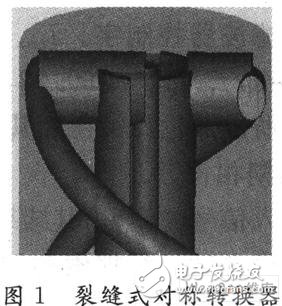
1 antenna model designThe dual-arm helical antenna is formed by using a parallel double-wire wound cylindrical dielectric rod, and the parallel double-wire is an open transmission line whose electric field extends to the outside. When the parallel double line is distorted, it causes radiation, and its feed point is 180° out of phase. Since the coaxial line is used to feed the two wires, the matching becomes critical, which is also a difficult point in the design of the antenna. A symmetric converter is needed between the asymmetric coaxial line and the symmetric spiral. Symmetrical converter), its structure is shown in Figure 1.
In the cylindrical coordinates, the helix is on the surface of the support rod with radius r0, and the spiral can be defined as:

It has periodicity in the ψ and z directions, and the model is shown in Figure 2.
2 Antenna analysis and performance studies
The current on the arms of the dual-arm helical antenna is approximately:

In the formula,
Let α be the integral variable, then the electric field formula is:

One of the arm phase terms is:

The meaning of the parameters in the above formula is shown in Figure 2. The electric field radiated by the two arms is superimposed in space to form the final pattern.

The simulation results of the dual-arm helical antenna model are shown in Fig. 3. In the design, in order to make the current as close to zero as possible at the end of the spiral, so that all the energy is radiated out, and the size requirements of the structure are compromised, the basic dimensions of the double-arm helical antenna, such as the radius of the helix, the radius of the dielectric rod, and the spiral, need to be optimized. Radius, pitch and number of turns and balancer groove depth 0.25λ. The calculation results show that when the number of turns is appropriate, the tail lobes of the dual-arm helical antenna are small, have a wide pattern, the beam width can reach above 10O°, the axial ratio is less than 3 dB in the beam width, and the azimuth is omnidirectional. Radiation, and gain of 6.1 dB, with good matching performance.
3 antenna test resultsAccording to the theoretical optimization design results, the double-arm helical antenna is processed. After testing, it can be concluded that when the standing wave is less than or equal to 1.4, the bandwidth is more than 10%; when the 3 dB lobe width is greater than or equal to 120, the axial ratio is less than or equal to 3 dB with a gain of 5.6 dB. Tests show that the dual-arm helical antenna can meet the requirements of the satellite navigation communication system, and the antenna has successfully implemented the satellite navigation communication test.
4 ConclusionA dual-arm helical antenna for satellite navigation communication system is designed. The antenna is optimized according to the electrical and structural requirements of the system. The test of the physical object and the successful application in the test show that the new dual-arm helical antenna can It satisfies the requirements of the inbound and outbound communication of satellite navigation communication system, and has high reference value for the design and research of satellite navigation communication system antenna.
The above is the Design of dual-arm helical antenna based on satellite navigation communication system we have listed for you. You can submit the following form to obtain more industry information we provide for you.
You can visit our website or contact us, and we will provide the latest consultation and solutions
Send Inquiry
Most Popular
lastest New
Send Inquiry
Privacy statement: Your privacy is very important to Us. Our company promises not to disclose your personal information to any external company with out your explicit permission.
Fill in more information so that we can get in touch with you faster
Privacy statement: Your privacy is very important to Us. Our company promises not to disclose your personal information to any external company with out your explicit permission.